 The complexity of a CNC machine can be overwhelming, even an Arduino CNC Mini Mill. Considering the mechanical, electrical, software and tooling aspects, it’s enough to make your head spin. It would be much easier to give up before you even start. Where do you begin? Believe me, I was right there with you. It wasn’t until I started to break the systems down that they started to make sense. For a basic refresher check out my What is a CNC Machine post. We will go into more detail here. When I attack a problem, I like to break it down in to manageable parts. That way I can focus on just one aspect of the project and not get overwhelmed with the larger task. I used the following break down
For a complete list of the parts I used check out the Mini Mill CNC Conversion Source Guide available here.
Arduino CNC Mini Mill – System Overview
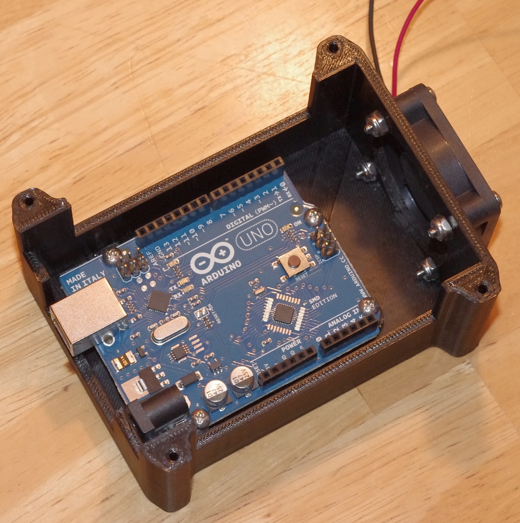
Part 1 – Electrical System – grblShield, Arduino, power supply, PC and stepper motors Click here to download a 3D printable enclosure for your Arduino & grblShield
Part 2 – Mechanical – Mini mill and CNC Fusion kit to convert the machine to accept the stepper motors
Part 3 – Main electronics enclosure & grblShield cooling setup
Part 4 – Full mill enclosure
Bonus – Future plans
Lets take a closer look at the electrical system
Part 1 – The Electrical System
This is what I would consider the CNC controller and the heart of the Arduino CNC mini mill. You can find a detailed how to post and a quick start guide to get your basic DIY CNC Controller setup and running here.
I started by loading the GRBL software on the the Arduino using the Arduino IDE. Next I loaded the Universal gCode sender software onto my Asus Netbook. I had to download the latest version of Java to get the Universal gCode Sender application to work.
Next I connect my power supply to the grblShield ensuring I had the polarity correct on the connection. Positive (+) to positive and negative (-) to negative. There are all kinds of warnings on the Sythetos website about making sure you don’t mess up the polarity. Apparently it destroys the grblShield and you need to send it back for repairs.
I switched on the power supply and confirmed the blue power LED lit up on the the on grblShield. Satisfied with my progress thus far it was time to connect the Arduino to the grblShield. Now, I have an older Arduino Uno and needed to move a jumper on the grblShield to get the correct logic level voltage. Not a big deal and you may not have to do this if you have a newer Arduino Uno R3.
With the jumper set, I dropped the grblShield onto the Arduino. I connected my netbook to the Arduino and powered on both the netbook and power supply. I launched the universal gCode sender application and confirmed connectivity with the grblShiled.
Finally, I connected a stepper motor and tested the entire setup. It was pretty cool to see the stepper motor turn the first time. You can check out a video here.
Click here to watch the video on YouTube.
Once the basic electrical system was setup, I focused my attention on the mechanical setup detailed in part 2.
Part 2 – The Mechanical System
The basic mill is a Harbor Freight Mini Mill Item number 44991 also called an X2. This was the natural choice for me. This low cost mill has a vast user group with many CNC conversion examples. I knew the upgrade to ball screws was a must but given the CNC Fusion kit is more expensive than the mill itself, I decided to see if I could find a used kit. I was happy to find a gentleman on CNCZone who was selling a used CNC Fusion kit for an X2.
I am not going to waste your time covering the installation of the CNC Fusion kit. There are plenty of examples on the internet. However, you may find the post I did about the problems I encountered with the Z-Axis setup and how to avoid them. Check out The Grind: A Z-Axis Problem for a few tips to avoid the mistakes I made.
The following is a quick video that walks through the complete setup.
Click here to watch the video on YouTube.
As you can see in the video, I still had all the parts an pieces laying on the bench. This was a great way to get everything setup and running but will not work as a long term solution. The answer, a nice electronics enclosure detailed in the next section.
Part 3 – Electronics Enclosure
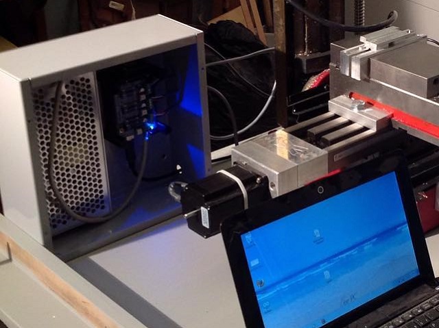
There are only a few items that need to go into the electronics enclosure and those include the main power supply, the grblShield, the Arduino and a fan. I went with a really nice metal enclosure from BUD industries available at amazon. Note the following is an affiliate link and I will earn a commission if you choose to purchase the box using the link. BUD Industries 10″ x 10″ x 4″ Sheet Metal Box
The 10″ x 10″ x 4″ box is the perfect size. Be prepared to drill your own holes for the cables. I purchased the version with out the knockouts intentionally so I could customize the hole size. You can also purchase the same box with knockouts that allow you to use a hammer and screwdriver to punch out locations to pass the cables through.
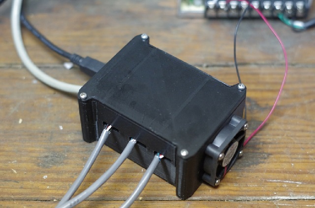
The most important feature of the electronics enclosure is the box that holds the grblShield and Arduino. Yes, I know there is a box within a box but it is very important. This allows the attachment of a fan to cool the grblShield and Arduino.
The fan draws air out of the box to keep the stepper motor drivers on the grblShield cool. The air inlet is on the far side of the box by the the USB connection. The enclosure was 3D printed at a local makerspace and includes mounting provisions on the bottom side. Note the lid is designed so that the fan stays attached to the enclosure while providing easy access to the connection points for the stepper motors. The fan is connected directly to the 24v power supply and powers on with the grblShield. A cad model of the enclosure is available for download by clicking here.
Part 4 – Full Mill Enclosure
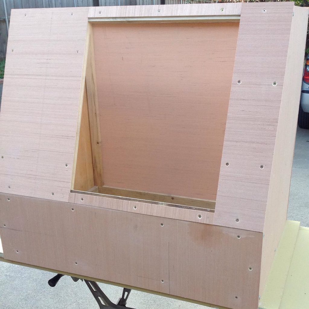
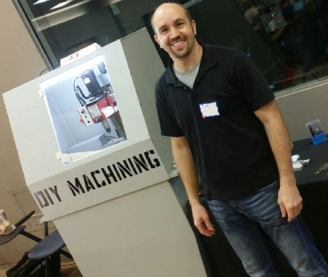
I really had not planned to make a full enclosure. However, the opportunity arose to take the mill to a local maker fair. I figured it would be poor form to have my machine sling chips all over the nice carpeted classroom. I spent a weekend building the enclosure pictured below. It’s constructed of 1/4 plywood and some 1 x 2s such that I can lift the entire enclosure off the top of the mill.
I added a coat of grey paint and an acrylic door. The stand is made from 3/4 plywood with casters to make moving the beast a little easier.
Future Plans
Now that my CNC mill is up and running, I cannot help but think about the next steps.
-
-
-
Raspberry PI –
I would really like to upgrade the CNC controller to use a Raspberry PI 2 as the machine controller instead of the ASUS netbook.
-
-
-
-
-
Jog Shuttle/Hot Key for Jog
Incorporating a jog shuttle of sorts would really help with part setup. At the very least a simple device to allow me to select between .1 (tenths), .01 (hundredths) and .001 (thousandths) of an inch to speed up the process of establishing my zero on each part. I wold be happy with a three buttons in Universal gCode Sender.
-
Power Draw Bar
The addition of a power draw bar would significantly reduce the time required to change tools. Nothing fancy, a pneumatic power draw bar with the belvelle washers to provide the clamping force.
-
Belt Drive
At some point I will also convert the plastic gear drive to a quieter & more reliable belt drive system. I am really just waiting for the plastic drive gears to fail. According to everything I read, it’s not if but when.
-
-
Final Thoughts
Thanks for sticking with me on that one. Hope you found something useful and perhaps you are planning your own Arduino CNC mini mill. If you have any questions feel free to e-mail me Tim@diymachining.com
Don’t forget to download the files to 3D print your own Arduino & grblShield enclosure.
Thanks for reading. Until next time… Tim


Nice, Starting to get the feel of it. Planning to dive in on my own CNC. Designer + CNC = Awesome Experience 😛
Arif – You are onto something! You will be a one stop shop for product ideas. Looking forward to see what you do.