
Do you have an initial set of values for your GRBL steps per mm settings? Are you ready to refine those settings to get even more accuracy from your machine? If so, this post is for you. If you do not have an initial set of GRBL steps per mm settings, no problem. Click here to generate your initial steps per mm settings.
Once you have an initial set of GRBL steps per mm (step/mm), we can begin to really fine tune the machine. Again, If you have not calculated your initial settings, click here. The method described below requires the settings be pretty accurate. We don’t want the machine to move 2 inches when we tell it to move 1 inch. We might break our measurement tool.
What You Need
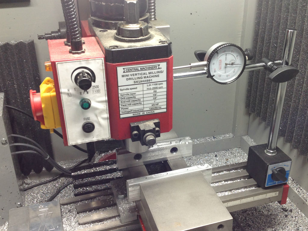
Before we go any further, you will need to have a dial indicator for this. I use the one shown below. It’s a low cost basic setup that will get the job done. You can find fancier more expensive indicators and bases.
Dial Indicator with Magnetic Base

Almost any dial indicator will work. If you have one already great, use that. I found that dial indicators with at least 1 inch of travel work best for this tuning process. Indicators with less than 1 inch of travel make the measurement distance too small. This causes the math below to be more complicated and sensitive to tiny variations in the indicator readings.
There are other ways to do this without a dial indicator but those involve machining a part and then measuring the part. Given the iterative nature of this process, it will take significantly more time.
Introduction
The goal is to tweak the GRBL steps per mm settings (step/mm) for each axis independently.
For example, my initial calculated settings were the following:
$100=314.960 (x, step/mm)
$101=314.960 (y, step/mm)
$102=78.740 (z, step/mm)
You can see how I calculated those by clicking here.
Once I finished the process of tuning each axis, the new settings were…
$100=316.220 (x, step/mm)
$101=315.361 (y, step/mm)
$102=79.136 (z, step/mm)
As you can see the settings are not significantly different. Nonetheless, I have noticed an improvement in accuracy of the machine. That is when I design a part in CAD to be 2 inched long, the finished machined part is much closer to 2 inched than before I made these updates.
Overview
1. Record the current GRBL settings
2. Tune one axis at a time
3. Set the dial indicator parallel to the axis you are tuning
4. Zero the dial test indicator
5. Zero the axis on the machine controller
6. Jog the machine 1 inch
Caution – Ensure you do not reverse direction of travel between zeroing the indicator and jogging the machine. This will cause the backlash of your machine to be included in the measurements and will cause problems.
7. Read the dial indicator to determine the actual travel of the machine
8. Adjust the GRBL steps per mm (step/mm) setting using the formula below
9. Confirm the GRBL settings were updated
10. Repeat the test starting at step 3 to confirm the new settings
How to Do It…
The first step is to record the current GRBL settings of your machine. If we make a mistake we can go back to these and start again.
This is done by powering on the machine and once a connection is established with the Arduino, type $$ into the command window of Universal Gcode Sender. This will print the current GRBL settings in the display window. Using the mouse cursor, highlight these settings and copy them to a .txt file. I am running Windows so I us Notepad.
Next, I set the dial indicator on my machine so I could measure the movement of the x-axis. See the picture below of the configuration I used for the measurement. Depending on the size and configuration of your machine, your setup may be different. Notice, I do not have the dial indicator contacting the spindle. I did this intentionally. The spindle is round and does not make a good contact point for the end of the dial indicator. Instead, I used a flat part of the mill head. This works because the spindle and head move together. The key is to get the dial indicator set parallel to the axis which you are tuning. We only want to tune a single axis at a time.
Once you have the dial indicator setup, jog the machine so that the dial indicator reads 0 with at least 1 of available travel remaining. I find it’s easier to jog the machine to zero the dial indicator than to turn the dial face because that tends to move the setup. Next, click the X zero button in Universal Gcode Sender (UGS) and then jog the machine 1 inch in the same direction using the machine control software. Confirm the digital read out shows the machine moved 1 inch.
Note – It is important that you move the machine in the same direction that you were going when you found the zero on the dial indicator. We don’t want to jog in the positive and negative direction to set the dial indicator to zero. This can cause the backlash in the machine to affect your measurements. You could end up chasing your tail. Not fun!
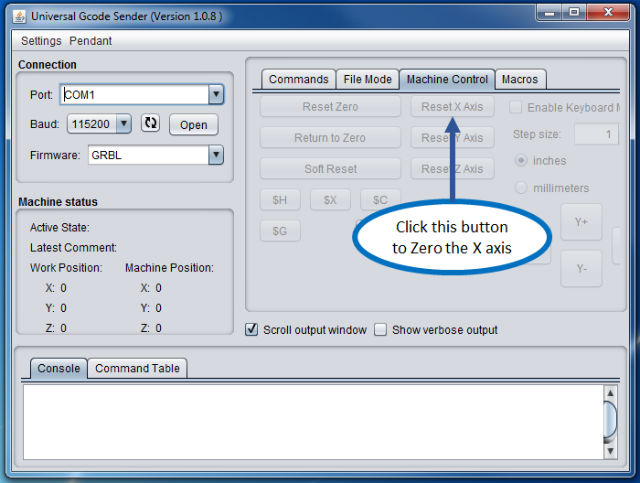
Machine Control Tab – Universal Gcode Sender (UGS)
In theory, having just told the machine to move 1 inch, the dial indicator should also read 1 inch. If it does, great you machine is perfect. You are done, no need to read or do anything further.
If not, then you will need to see how much the dial indicator actually reads.
In my case, the indicator read .997” which tells me, the machine traveled .003 inches less than expected. Therefore, I need to increase the number of steps/mm. You may be asking how do I know how much to change the steps/mm setting?
There is a simple formula for that…
Updated Steps/mm = (Current Steps/mm) x (Commanded Travel) / Dial Indicator Reading
Current Steps/mm – The current GRBL settings
Dial Indicator Reading – The actual distance traveled by the machine
Commanded Travel – The distance the machine was told to move form the computer interface
Updated Steps/mm – The new value you enter into GRBL
This can be further simplified if you always command the system to move 1”.
Then the formula becomes…
Updated Steps/mm = (Current Steps/mm) / (Dial Indicator Reading)
I realize this is might be counter intuitive, it was to me until I took a step back and thought about what was happening. If your actual measurement from the dial indicator is less than expect, it means you need to increase the steps per mm setting. Your machine controller gets a command in distance and then calculates how many steps to turn the stepper motor. GRBL uses this step/mm setting to make that calculation. If this value is smaller that needed, fewer steps per a unit distance, then the calculation will say it takes fewer steps to move the desired distance.
It can take a few minutes to wrap your head around. Feel free to experiment with different settings on your machine. You can always change them.
This is an iterative process and I had to do this a few times until I could get repeatable results. Once you have the new GRBL steps per mm value from the equation above, update the GRBL settings.
For the X axis, this is done in the command prompt of Universal Gcode Sender by typing $100 = “the new value” without the quotation marks and then pressing enter. Confirm the setting was updated by typing $$ into the command window. This will print the current GRBL settings.
Once you have the x-axis dialed in, you can move to the y and z axis. These follow the same process described for the x axis. The only difference will be the dial indicator setup. Remember, we want the dial indicator to be parallel to the motion of the axis we are tuning. See the photos below for the dial indicator arrangements I used.
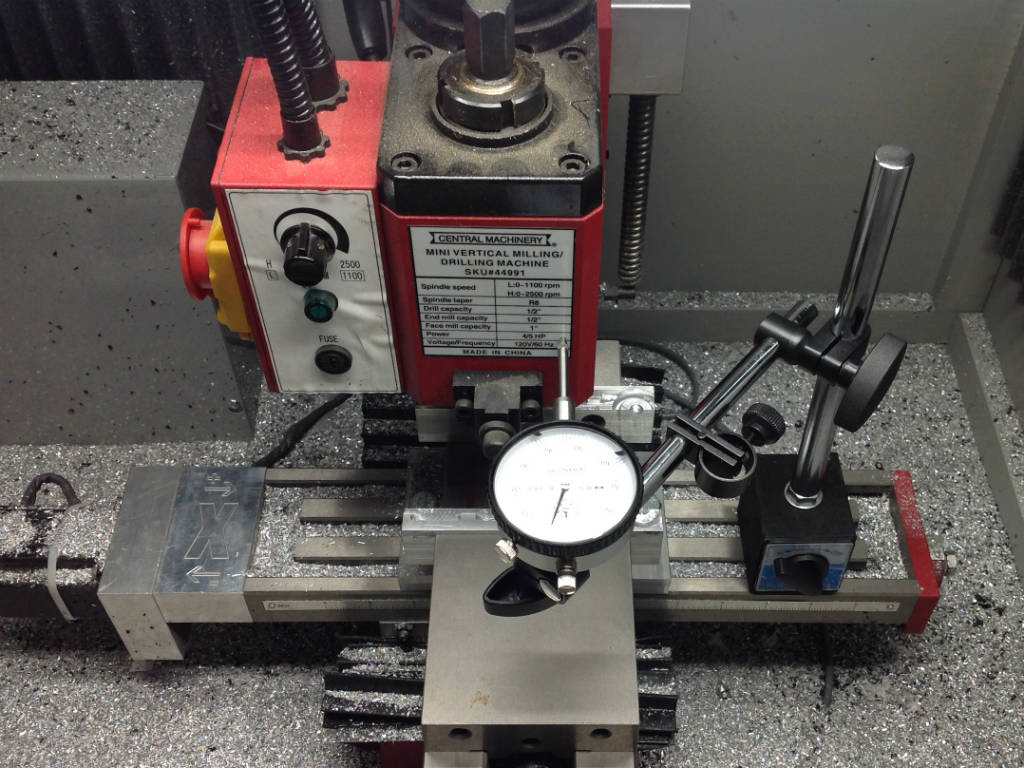
Dial Indicator Setup to Measure Y Axis Travel
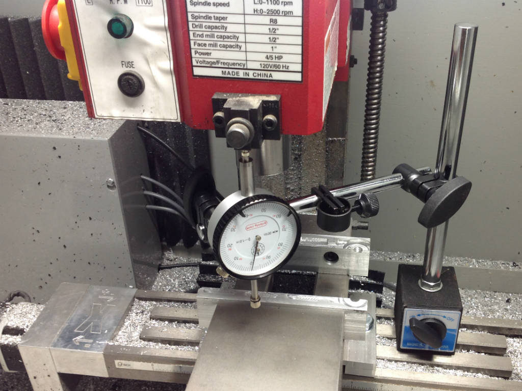
Dial Indicator Setup to Measure the Z Axis Travel
Conclusion
Now that you have your GRBL steps per mm set, its time to run a quick Gcode program to test out the new setup. Click here to download example gcode program that will move the spindle in a 1 inch diameter circle. if you add a marker or pencil, the machine will draw a 1 inch circle.
If you have any questions feel free to leave a comment below or send an email to me Tim@DIYMachining.com
Thanks for reading. Until next time…
Tim
Tim,Just want to say man I started all my cnc stuff after reading your post and website. I have been doing this for about a year now. I started out with a desktop router. I was researching different machines such as the x2. I now have hf mill I picked up used. I also had some random nsk ball screws and some smaller nema 3 motors that were given to me laying around.
First off the x2 conversion was way more difficult to do than a cnc router. I get my zencnc setup was purchased ready to go but man I couldnt imagine someone with zero to very little actually successfully converting a mini mill and successfully producing quality results. It took me about 4 months to get to where im at now. I started from scratch and designed all parts in fusion and made them on my router. I got my machine moving a couple months ago with my random ballscrews ( nsk1605) and nema 23 296 oz diven by tb6600 stepper drivers.
I first want to say that I feel like disregarding backlash is insane. From this article it would make one to believe you could make parts accurately without dealing with backlash.we are dealing with such precise accuracy that even .001 backlash from an axis will make a part horrible and maybe un acceptable. I think before you even ty to dial in steps/mm you need backlash to a point where over .01″ its not moving hardly a 1/10 of a click on the dial. if it is and you are running a gcode file then boom it gets amplified. causing the person to have weird looking not to scale parts as well as destroying the stock and endmill potentially. The reason Im bringing this up is I have been struggling with backlash latley and I just recently realized thats what i was struggling with. I learned everything else trying to fix my issues. I now have backlas under control. But I guess my point is that backlash is more important than making sure your steps/mm are on. yes you can dial it how your saying but when milling your machine isnt gonna go one way. and if your backlash is constintly changing every tie it switches directions then you are gonna have some major issues. Lets now think about what backlash is. Back lash is faulty or inproperly installed parts (mill or conversion kit). There are soo many little things that one must learn before they will even understand backlash. The most simplest things such as couplers, lead screw end nuts not being tight enough or things not aligned all cause backlash. Or adjustments on the mill .
Anyways my point is, Tim thanks for everything you have taught me. Even tho most of the time I had no idea what you were saying and I just went for it. Shoot when I started I had no idea there were 3 parts to cnc. cad, cam, gcode. and thats just the computer stuff. I guess what I was trying to say is that backlash is worthy of talking about. yes you can get you steps/mm dialed but you still will have crap results unless you figure out the underlying issue of backlash. But after talking through this I have realized that its upon the reader to dig deeper. you are just skimming the surface with your articles. Your articles are there to give the reader a direction.
oh now what about switching to mach 3 ? man then everything i just talked about is useless due to the fact that mach 3 has backlash compensation. This is where I now am stating to realize that grbl is held back by the uno. We can only dream they move to another piece that will allow us to do things like compensations and still have availability and cost. also I wanted to ask you if you have ever thought about your drivers. Have you ever wondered hmm maybe I can get more with larger stepper drivers? also what about upgrading the power to say 48 volts. Its kinda hard to say those drives are do anything good unless you know what its like to run at whats called for. I only ask this due to me using 3A steppers and tb6600 drivers which say they go to 3.5A but I feel they are more around 2.5-3A which is way to slim for me. I initially tried using some tb6560 drivers rated at 2.5a and they were horrible compared to the 6600 which I feel are still crap and I need larger.
anyways sorry about the long ramble hope it makes some sense. also thanks again. I would have never been able to learn and do what i did without a sweet website to reference all the time ( well I have all of the article printed out).
Hi Chris, great comment. Ah yes, backlash. This is the bane of every CNC machine in the world. This gets even more complicated when we add the concept of lost motion (ie missed steps from the stepper motor). You are correct, GRBL does not have any backlash compensation where as LinuxCNC and Mach3 do. Interestingly, backlash compensation is still really a bandaid solution and does not address the underlying problem. Given the cost target, I am willing to accept some backlash in the system. When my mill was new, I measured 1 or 2 thousands (.001 or .002) on the X, Y and Z axis. I know I am not making aerospace parts. I notice the backlash most when I go to helically interpolate a hole.
You are calculating steps per millimeter, but using inches to refine your settings (movement reading on dial indicator is in inches, but you are setting steps per mm.)
Wouldn’t you have to convert your dial indicator reading to mm before doing any of the step/mm calculations?
Hi Tom, good question. If you look at the formula, we are multiplying the steps/mm value by a unitless relative value, the inches units cancel. The commanded travel is in inches and the dial indicator reading is also in inches. Now just be sure you don’t command a value in mm and then read a dial indicator reading in inches. That would certainly cause problems.
Hi Tim…
How do you account for the difference between the calculated steps per mm and the calibrated value? The only thing i van think of is that the leandscrew pitch is off, and that could vary along its length. Am I missing something?
Hi Ed, great to hear from you. Yes, that is one of the potential error sources. I also expect there are also small variations in the stepper motors and drivers.
Hi Ed,
Nice post. If you have the time, have a look at the Setup Wizard in Universal Gcode Sender (Platform edition) and let me know what you think: http://winder.github.io/ugs_website/guide/platform/#setup-wizard
It has a page for calibrating the machine in the same you are describing.
Joacim, good tip. I have not spent any time with the setup wizard in UGS Platform. I got so used to the classic version it’s been a fight to make the change to Platform.
I’ve been using your new setup Wizard and love it. My x-axis was quite off. Z and Y were fine. I have a problem though. My CNC machine appears to need a different calibration in one direction than the other. The toothed cable appears taught. The collar on the stepper motor is tight. Not sure what else could cause this.
Have you heard of the need to calibrate differently in each direction?
In your calibration wizard the movement of axes is one direction are greyed out. So you only want folks to calibrate in one direction? Or am I doing something wrong?
Would like to be able to calibrate in the other direction to check whether my assumption is correct
Hi Douglas, thanks for posting a comment. First, I cannot take credit for the Setup Wizard in Universal Gcode Sender (UGS). I am not the developer of the software. I simply found the software useful and shared it here. All the credit goes to those who developed UGS and contributed.
To address your questions about calibration in both directions, I only know how to set one calibration value for a given axis. The software assumes the number of steps to go 1 inch in the positive x direction is the same as the number of steps to go 1 inch in the negative direction. In almost all mechanical systems there will be some lost motion when we convert rotational motion to linear motion.
Typically, we will see the lost motion when the axis changes from a positive to negative motion (or vice versa). You can measure the lost motion with a dial indicator. Move the machine in the positive direction and depress the plunger on the dial indicator. Note the reading on the dial indicator and jog the machine in the opposite direction. It’s best to have the jog distance set to .001″ (or the finest resolution of your machine). You count how many times you need to command a .001″ jog motion before the dial indicator registers any movement. This is the lost motion in your system.
I am running ball screws on my machine so I do not have any first hand experience with the timing belt system used on your machine. I would see if the axis move freely with out binding. You can remove the stepper motors and manually move the machine through the extents of the travel to check for any spots that bind. I had to spend some time adjusting my machine to ensure the Z axis travel was smooth and did not bind. If you get any binding, you will loose steps. That is the stepper motor is commanded to move but due to a mechanical bind, the stepper does not actually move. Since these are open loop control machines, the software assumes the machine has moved.
Feel free to reach out again if what I described above is unclear or you have additional questions.
thanks for the tips. our Y axis has 2 motors. Is there any way to individually calibrate for each Y motor? (ie. $101a=40.001, $101b=39.997) because, without this, each belt can produce different lengths and introduce shear. If not, the Y software calibration is pretty much useless. Better hack the machine with adjustable belt tensioners (screw/nuts) and go with trial and error.
Hi Constantinos, not with GRBL. The only calibration you get is X, Y & Z. You would need to find a more advanced CNC controller or like you said look at a mechanical solution.
Hi, i assembly a 5 ft x 8 ft table cnc , but the size of the printed is different to the plans information
i create the plans on ink scape and if i draw a 3×3 inch , the result is 10 x 10 inch
i am using an arduino uno witn grbl, can help me to know how to adjust the steps/mm ? or is another adjustment? thank`s
Good question, I recommend you run the sample Gcode program found here. This will tell us if the GRBL settings need to be adjusted or if there is a scaling issue in ink scape.
There is a scaling setting in inkscape that inevitably changes to 3.xxx instead of 1 like i am constantly setting it to. it is in file>document properties. be sure you are going back in every few clicks and resetting it to 1 before you export/gcode
Hi, this site has been of so much help i cannot thank you enough. I have an old Chinese CNC j-CUT 1325C machine that i managed to switch the controller to arduino UNO with GRBL v1.1 because the old controller required a weird 15pin game connector and control card. Anyways, after running it several times, I realized that it is not running square and due to its construction there is no way to physically do it. The Y axis has two stepper motors attached to it, is there a way to wire them on the arduino to individual pins and run some sort of squaring on GRBL? currently the stepper drivers on Y1 and Y2 are wired to the single Y output pin and then the coils are inverted on the different motors. Any thoughts on this situation?
Tobias, glad you found the site helpful. Unfortunately, GRBL does not include the type of feature you described.
Hi Tim-
Let me first thank you for your great tutorials and this one, in particular!
I want to do some delicate work in aluminium using my original, or ‘classic’ (v.1) Nomad 883 desktop CNC mill. Fusion 360 and adaptive clearing has brought some new life into the mill as has the discovery of cast tooling plate aluminium. A friend of mine sent me a link to your web tutorial and at first I thought that your protocol would be perfect for calibrating the X and Y precision of the machine. That is, until I noticed that you’re using a long stroke plunge dial indicator, while I have a small dial test indicator .
Could you think of a clever way to modify your protocol so that I can measure sufficient travel (>1 inch), but using my dial test indicator instead of your large plunge dial indicator? (I’ve also posted this question on your web page)
Many thanks in advance and stay safe!
-Peter under lockdown in the UK
Peter, I appreciate you leaving a comment. I replied to your email and wanted to post the same response here as well so others can reference the information. The calibration procedure can be completed without a plunge style indicator. However, you will need another measuring device like a pair of calipers. The dial test indicator does not have the required travel to produce a reliable calibration.
Start by drawing a pair of parallel lines on paper or card stock. By measuring between the lines with your calibers or even a good ruler you could get pretty close. The goal here is to get close to the final calibration and verify the calculated value.
Once you are close, I would recommend machining a few rectangles and measuring those with the calipers.
Does that make sense? Let me know what you end up using to calibrate your Nomad
Hi Tim! Building a cnc lathe. I encounter a problem when I jog more than 1in increments. If I go to 6 inches at 1in increments its .003 or so. If I tell UGS to jog 6in at once I get +.200 :/
If I use the formula to adjust for the 6in jog, the 1in jog falls short.
Less than .005 error would be amazing for my wood projects. Thanks in advance
Hi Ian, glad you reached out. That is a puzzling problem. I suggest you investigate two potential causes. 1 – Mechanical binding at some point in the 6″ travel range. For example, is it possible the machine binds between the 4″ & 5″ position? You could test this by running the 1″ jog test starting at 1″ increments of the range of motion for the given axis. If you get ~ .003″ of lost motion for each test, it’s probably not a mechanical binding issue. 2 – Lost steps due to acceleration or max feed rate exceeding the limits of the system. Have you tried commanding a 6″ move at a low feed rate? If you can successfully move 6″ with out significant loss of motion at a slow feed rate, you are likely loosing steps when the machine tries to accelerate or move faster then then system will allow. You will need to adjust the max feed rate or acceleration in your GRBL settings until you don’t see any more lost motion. Let me know what you find.